Repairing Grid
Using this guide you'll be able to reliably disassemble your Grid module for repair or for using an Upgrade Kit.
What you'll need for a repair
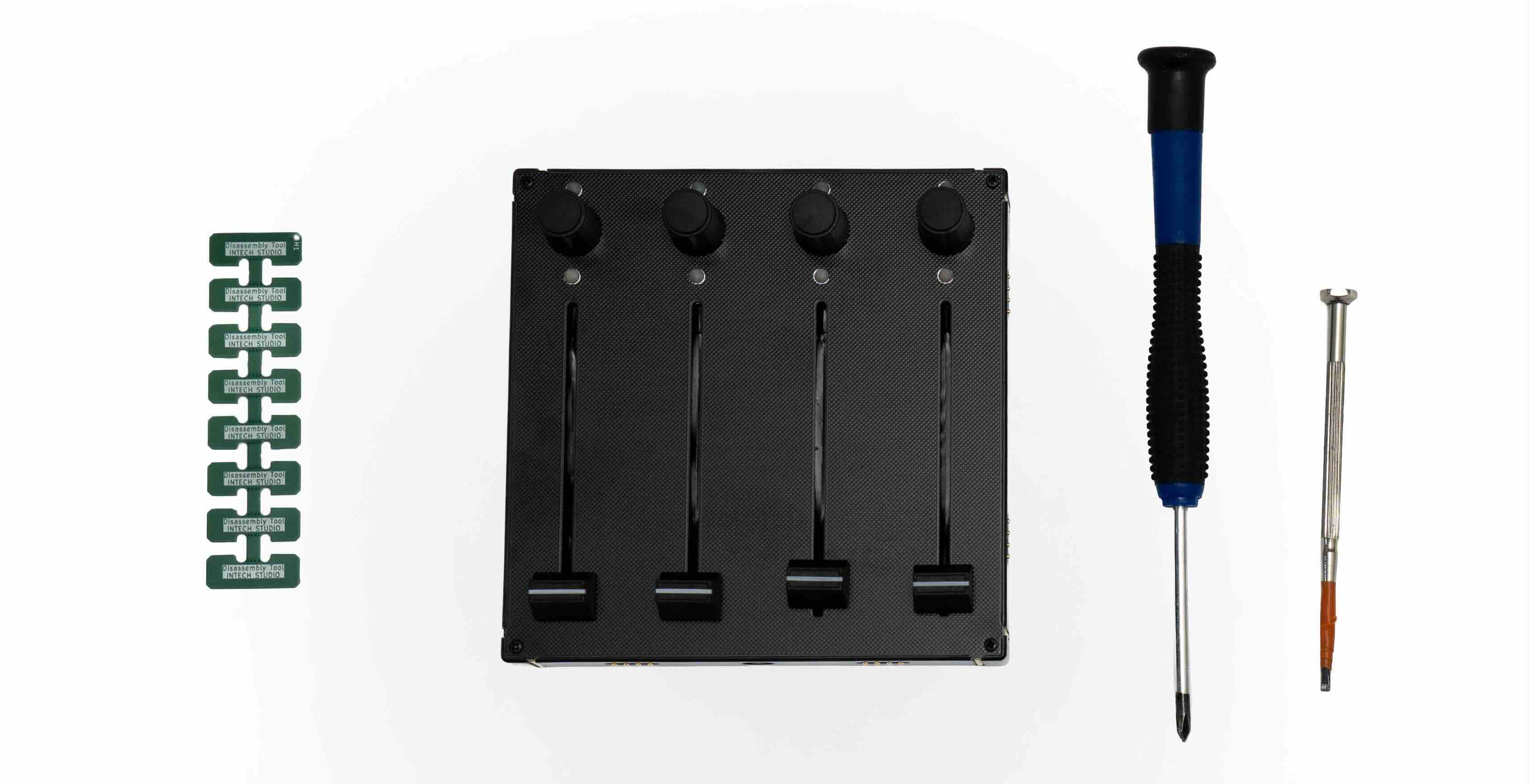
The tools for this job are listed below:
- An Intech Studio Grid module, manufactured after May of 2023 (no visible logo on front panel);
- A Philips-type, size-1 screwdriver;
- A set of disassembly picks (comes with the motherboard or the interface PCBs meant for repair);
- A tool to lift the potmeter caps (eg: flat headed screwdriver, guitar pick);
- A set of replacement parts if needed.
Choose a clean, non-conductive surface you can comfortably work on, the whole process shouldn't take more than 10 minutes!
Disassembly of the EF44, PBF4, EN16, PO16
Follow along with the video for your module type.
Disassembly of the TEK2, VSN1, BU16
Follow along with the video for your module type.
Disassembly Tips
- When lifting the potentiometers, you can use a flat screwdriver or a guitar pick — slide it underneath and gently push up, which makes it much easier to pull out.
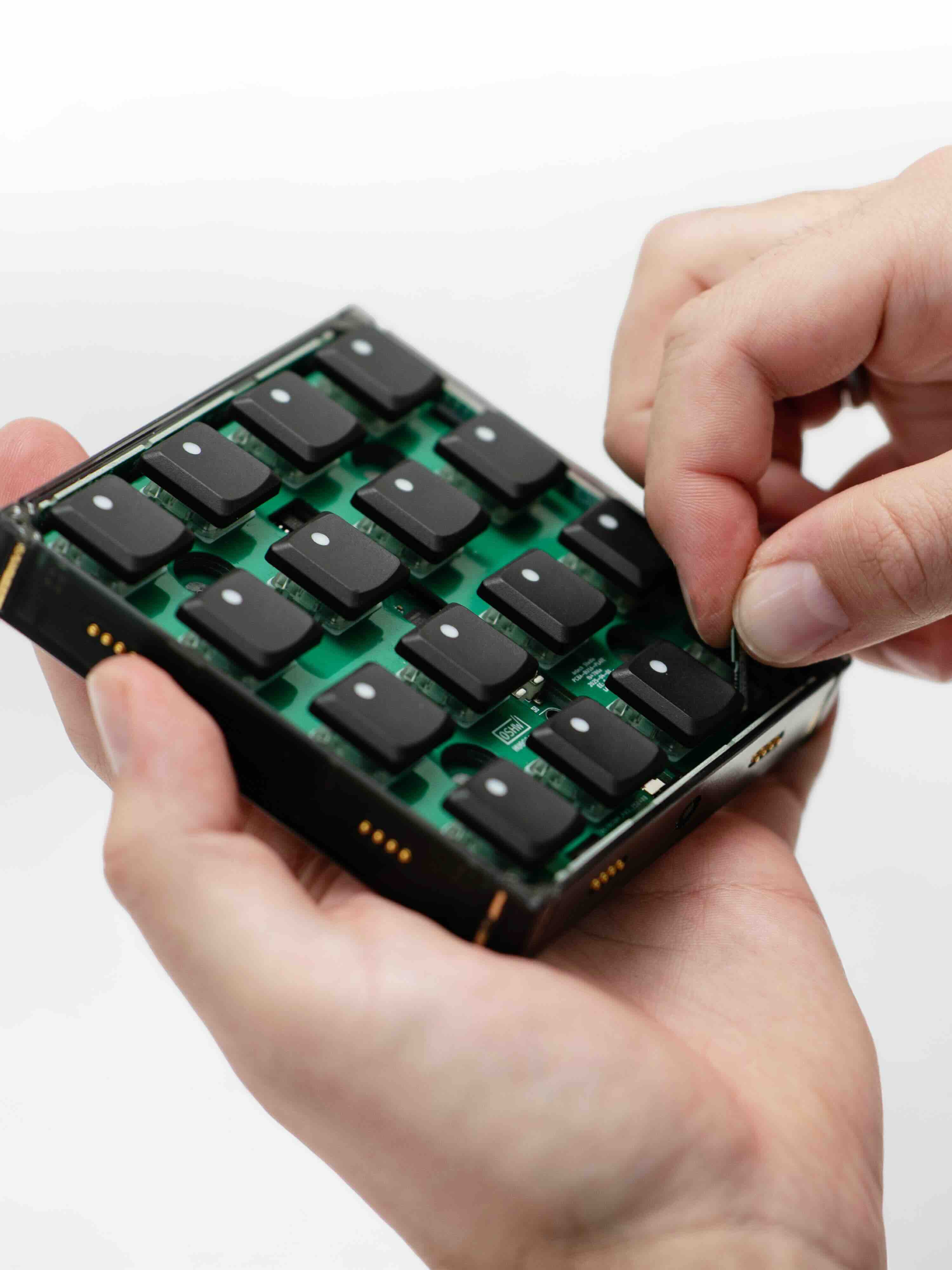
- The interface board pins hold the motherboard in place, so you need to push the small pin holders on each side down while tilting them slightly outward to release it.
- When removing the motherboard, gently lift the PCB by pulling on one side or by lifting it through the hole in the main PCB. Angle it carefully to avoid damaging the two white buttons next to the hole.
Repair of interface (side) PCBs
If you're having trouble with getting one of your Grid modules to connect to another over one of its sides, you might have a faulty interface on your hands.
Check in with Intech Studio Support before you start trying to repair your device, to make sure your issue is something you can fix at home.
In some cases we'll have to provide you with spare parts or tools for disassembly to get you started.
Write to us: [email protected]!
In most cases the interface board is not actually faulty or completely dead, it's just improperly seated. Follow the advice from Intech Studio support on how to proceed!
Fixing a misaligned interface PCB
If a module is not recognized by Grid Editor, the side connector pins may have become misaligned. Follow the steps below to see how to inspect and gently realign the pins to restore communication.
- Identify which side is not connecting;
- Partially disassemble the module until you can access the interface PCBs, follow the steps here or here;
- Hold the side interface board with one finger and carefully put some distance inbetween the PCB and the plastic cover of the connector (see the GIF below), doing this will gently bend the pins back into place;
- Test to see if the connection improved before re-assembly.
Fixing a 'dead' interface PCB
Rotating the suspected module and checking which side would not connect with a second Grid module is the best way to know which side is the faulty one.
Remove the faulty Interface PCB by following the disassembly guide and replace it with a replacement one you received from Intech Studio support.
-9aebf6a54d95f4b7643c612c02aca1ce.jpg)
Troubleshooting
Regarding things that may go wrong during disassembly:
- If the copper connectors on the inner side of the interfacing PCBs become bent or deformed: don't be afraid to bend them back into place by hand.
- If a bronze nut falls out of the bottom of the plastic shell or becomes loosened: try to put back in/hold it in place with a second screwdriver;
- If plastic scraps or residue fall out of the caps when removing them for the first time: after reassembly, check if the caps touch or scratch the front panel, if they do email us at [email protected].